|
|
||||||||||||||||||||||||||||||||||
|
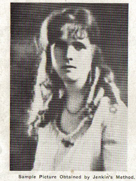
The Jenkin´s System In the latter part of 1922, the first radio picture was transmitted by the Jenkins´ system. This picture was transmitted from the inventor´s laboratory in Washington, D.C., to his home, located in the same city. The outstanding feature of the Jenkins´ system is the use of a prismatic ring for analyzing the surface of the picture to be transmitted. A beam of light, when passed through a rotating ring of this type, is caused to oscillate, having its hinged section, or line of action, fulcrumed, in the plane of rotating of the prism ring. The oscillation is always in the plane of the diameter of the disc, from the point where the light passes through the prismatic ring section. By the use of two of these rings, a beam of light can be thrown up and down, and from one side to the other. If both tansmitter and receiver rings are rotating synchronously, the receiver beam will always be in the same part of the picture as the transmitter. As early as 1894, he outlined a scheme for the electrical transmission of pictures. Other high spots in his career include his proposal on September 27, 1913, of wireless moving-picture news; and in 1923 he transmitted pictures of President Harding by radio from Washington to Philadelphia, 130 miles. In December, 1924, clear images of the signature of Herbert Hoover, then Secretary of Commerce, were sent from Washington to Boston, 450 miles. From pen-and-ink photoradio Jenkins turned to television, and on June 13, 1925, in Washington, he demonstrated a mechanical scanning system using a revolving disk, the rim being lined with tiny lenses. Collaborating with the Navy, in 1926, he flashed weather maps from Arlington, Virginia, to ships at sea, using a mysterious radio "pen". In March, 1932, he described a new principle far advanced from the early shadowgraph stage. Now the images, estimated to be 3,600 times brighter, appeared on a sensitized emulsion on an animated lantern slide. Incoming signals quickly changed the surface from opaque to clear, equivalent to the lights and shadows, thereby painting an ever changing pattern corresponding to the scene transmitted. Several of the Jenkins motor-driven mechanical scanners were demonstrated in New York; the receivers had a large glass bullseye like screen. Through this instrument many people witnessed television for the first time during the early thirties. Jenkins died on the threshold of television
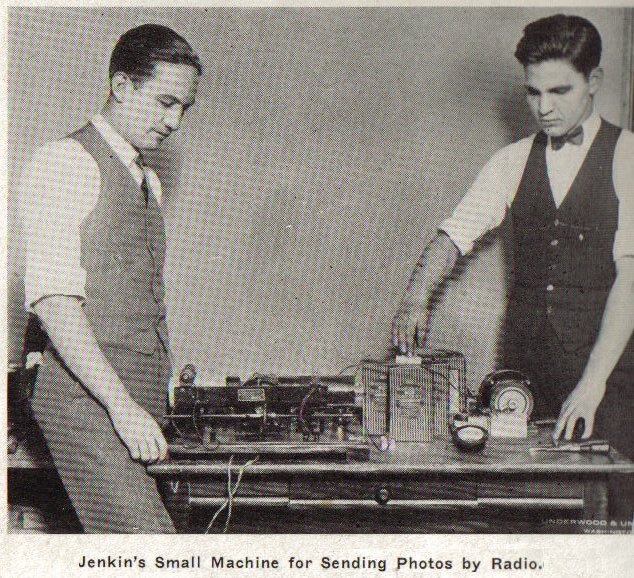
By means of a projection lantern and a transparent negative, the transmitter analyzes, or slices, the picture, and passes the beam of light from the source, on through to a photoelectric cell. This cell is arranged so that it converts the light variations impressed on it into electric energy, which in turn modulates the carrier-wave of the transmitter just as the voice frequency modulates the carrier-wave in radiotelephony. The signals picked up that the receiver are applied to a pneumatic oscillograph, which reflects a beam of light through a set of prismatic rings. The ring allocate the light to its proper position on the flat recording plate. The pneumatic oscillograph is a very clever intention of Jenkins´ and is simply a radio headphone, with a mirror mounted in a small cap opening. The air pressure caused by the displacement of the diaphragm, causes the mirror to move and the beam of light is correspondingly shifted. Synchronizing in the Jenkins´ system is accomplished by synchronous motors driving the prismatic rings. In circuits where the transmitter and receiver cannot be supplied with the same alternating current for driving these synchronous motors, small dynamotors are used, their speed being maintained constant by electrically driven tuning forks.
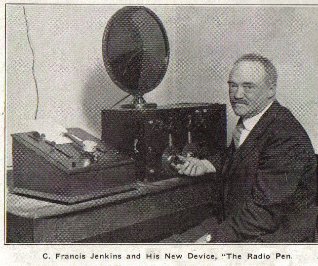
The contacts of these forks are placed across the A.C. end to the dynamotor. Since both the fork and the A.C. generator have the same frequency, any attempt of the D.C. motor to speed out of phase, is checked by the torque to the coupling shaft to the A.C. machine. A Radio pen which writes and draws pictures, tracing exactly the same lines as those laid down by a distant hand, is another device invented by C. Francis Jenkins, Washington, D.C.
(C) Marius Rensen
|
|
[History] [Historical] [Korn] [Jenkins] [Bartlane] [Belin] [Gray] [Caselli] [Hummel] [Progress of Wire Facsimile] [Start of Radio Facsimile] [Commercial Point to Point] [Broadcast] [Facsimile Tape] [Comparison of Wire and Radio] [Radio Propagation] [Radio Facsimile Systems] [Scanning Equipment] [Mechanical Scanning] [Recorders] [Synchronizing] [Facsimile Tape] [Machine Design] [Multi Channel] [Color Facsimile] [General] [Conclusion] [Inventors] [Facsimile Makers] [Patents] [Home] [Home] |