|
|
||||||||||||||||||||||||||||||||||
|
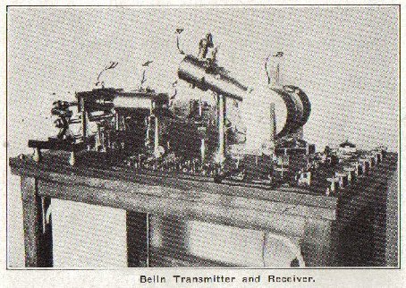
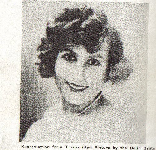
The Eduard Belin System Modulated systems. The Belin method The Belin method, invented in 1908, was primarily designed for use on land lines. It was not used over radio circuits until 1922. In the Belin system what is termed a ŌĆ£reliefŌĆØ cylinder, is used to carry the picture for transmission, rather than the varying light method produced by shining a light through the transmitting film, as in the cases of the transmission systems previously described.
The relief cylinder is made by taking an ordinary negative film, and printing through it, with a strong light, on a carbon-gelatine-bichromated paper. Upon development, the gelatine is swollen, due to the fact that the printing has baked the clear parts, hard, permitting the places where no light struck, to become soluble in water. This print is transferred to a brass transmitting cylinder, and permitted to dry. When dry, it will be found that the lighter shades have practically no relief, and are down to the brass itself, while the darker tones attain a height proportional to their photographic value. The overall relief is some five thousands of an inch. Pressed against the cylinder, is a stylus, similar to a phonograph needle. This stylus rises and falls as it passes over the rotating cylinder, and this motion is transferred to the diaphragm of a microphone. The microphone is of the carbon granule type with a very thin diaphragm. Very little resistance, therefore is offered to the needle, thus preventing the scratching of the relief cylinder. As the diaphragm of the microphone moves up and down, the internal resistance of the microphone changes in accordance with these vibrations and a current, modulated in character, is produced in the microphone output circuit. The modulation frequency, which we may call ŌĆ£picture frequencyŌĆØ, is very low, being from one to one hundred cycles. This frequency would be very inefficient if introduced directly into the modulation circuit of a radiotelephone transmitter so it is first used to modulate the output of a six hundred cycle tuning fork, which is turn, modulates the radio-frequency carrier wave. These radio signals are received by an ordinary radio receiver, care being taken to provide for an efficient audio-frequency amplifier for the six hundred cycle modulation frequency. In the output circuit of the audio-frequency amplifier, there is a step-down transformer to step down the voltage and step up the current for maximum effect upon the armature of the receiving oscillograph.
(C) Marius Rensen |

|
[History] [Historical] [Korn] [Jenkins] [Bartlane] [Belin] [Gray] [Caselli] [Hummel] [Progress of Wire Facsimile] [Start of Radio Facsimile] [Commercial Point to Point] [Broadcast] [Facsimile Tape] [Comparison of Wire and Radio] [Radio Propagation] [Radio Facsimile Systems] [Scanning Equipment] [Mechanical Scanning] [Recorders] [Synchronizing] [Facsimile Tape] [Machine Design] [Multi Channel] [Color Facsimile] [General] [Conclusion] [Inventors] [Facsimile Makers] [Patents] [Home] [Home] |